共焦 Raman:原理与模型边界
Confocal Raman: scientific basis and limits
这是参考 Renishaw inVia 共焦显微拉曼结构制作的独立教学应用,不是 WiRE 软件、原厂数字孪生或真实仪器控制。显微镜、可选遮光罩、物镜、机械尺寸、载物台行程和光路剖视均为示意。原厂不同配置的激光、物镜、滤光片、光栅、探测器及安全等级可能不同。[1,2]
This independent teaching application is inspired by a Renishaw inVia confocal Raman microscope. It is not WiRE software, a manufacturer digital twin or a hardware controller. Microscope, optional cover, objectives, dimensions, magnified stage travel and optical cutaway are illustrative. Manufacturer configurations differ in lasers, lenses, filters, gratings, detectors and safety classes. [1,2]
外观照片与本次修订
Photographic exterior references and revision
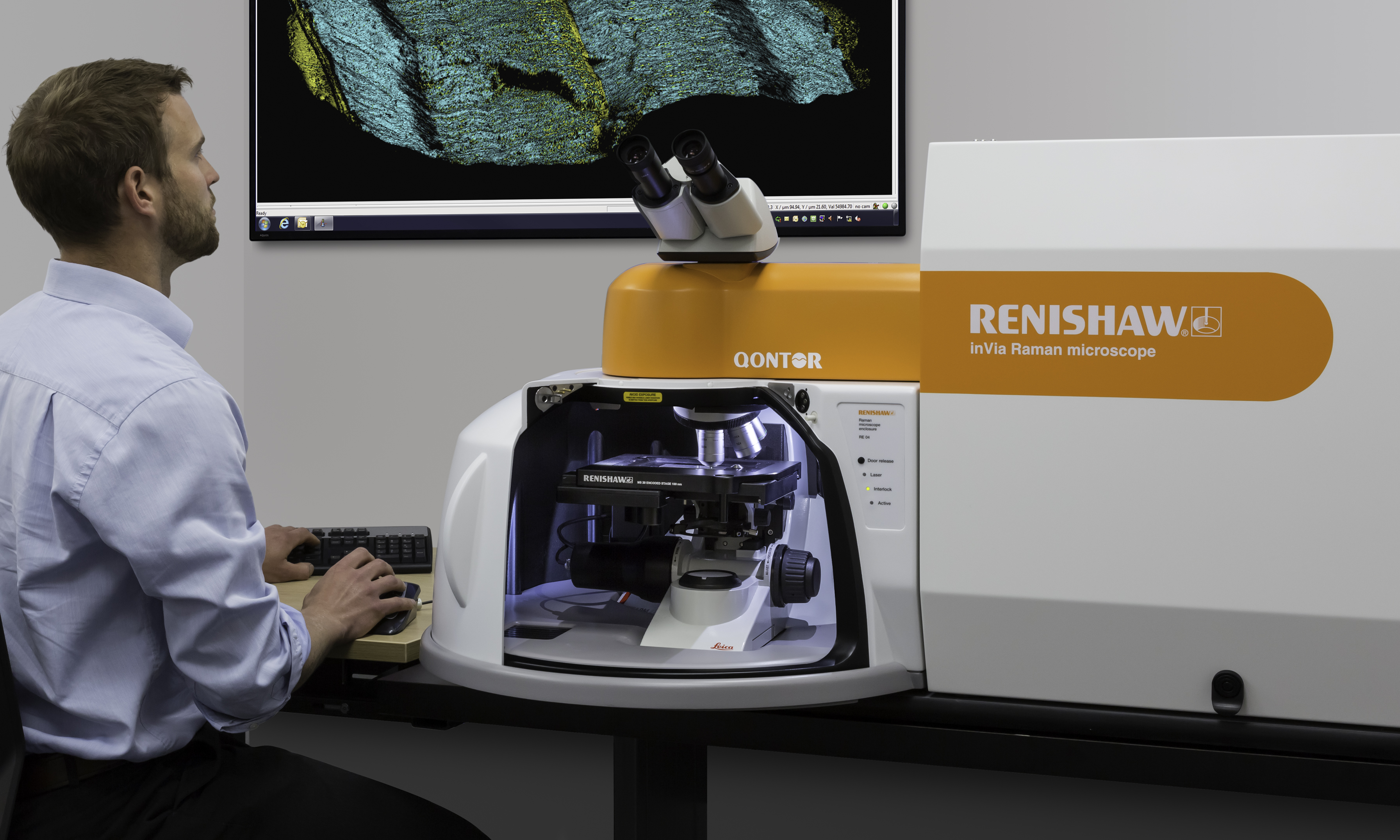
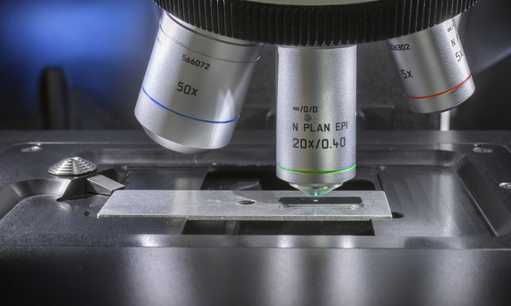
外观依据 Renishaw 官方 inVia Qontor 整机、样品舱和物镜近照重建:橙色圆弧光学头、白色包围式样品舱、倾斜双目镜与带橙色侧板的主机。转盘以倾斜五位置构型展示,保留三种可选物镜及空置接口;工作物镜切换后仍与样品光轴重合。外形比例并非原厂尺寸;圆弧收拢的罩门动画为教学运动,不代表厂商门机构。外罩剖开后展示的内部光路仍是功能示意。
The exterior is reconstructed from official Renishaw photographs of an inVia Qontor, sample chamber and objectives: rounded orange optical head, white wraparound chamber, inclined binocular head and integrated spectrometer with an orange fascia. An inclined five-position revolver displays three selectable lenses and vacant ports; every active lens remains coaxial with the sample. Proportions are not factory dimensions. The curved cover animation is illustrative motion, not a claim about the manufacturer's door mechanism. Internal optics remain a functional diagram.
- Renishaw inVia product page and official photographic references
- Official whole-instrument photograph
- Official objective and sample-stage detail
1. 正确的光学关系
1. Optical relationships
激发光经物镜聚焦到样品;同一物镜收集背散射光。二向色分光组件将收集光导向 Rayleigh 滤除、分光光栅和探测器。剖视图保持这条功能链,但不是原厂工程光机图,器件剖视不计算光线追迹、共焦孔径、滤光片透过率或实际空间/光谱分辨率。原理工作台另有明确假设参数的光栅演示,不是这台仪器的标定。图中光线沿直线段传播;空气中发光线条、光子亮点和收集光色彩均为教学伪色。785 nm 是近红外,紫色显示不代表其可见颜色。[1]
The objective focuses excitation onto the sample and collects backscattered light through the same lens. A dichroic splitting arrangement routes collection through Rayleigh rejection, a diffraction grating and a detector. The cutaway preserves this functional chain but is not the manufacturer's engineering layout. The instrument cutaway does not calculate ray tracing, confocal aperture, filter transmission or actual spatial/spectral resolution. A separate principles demonstrator calculates grating geometry with explicit assumptions, not instrument calibration. Rays follow straight segments; glowing paths, moving photon markers and collection colours are false-colour teaching overlays. 785 nm is near-infrared; purple does not represent its visible colour. [1]
采用 Δν̃ = 10⁷ (1/λ₀ − 1/λₛ),波长单位 nm、拉曼位移单位 cm⁻¹。Stokes 光的 λₛ 大于激发波长 λ₀。采集模型仅显示 100–1800 cm⁻¹ 的 Stokes 区域;原理页另行计算 Rayleigh 与 anti-Stokes 的能量和波长,不生成相应的仪器采集光谱。切换激发波长只改变波长换算和示意颜色,固定模式的拉曼位移不变,跨激发波长的强度不能用于比较。
The conversion is Δν̃ = 10⁷ (1/λ₀ − 1/λₛ), with wavelengths in nm and Raman shift in cm⁻¹. Stokes light has λₛ greater than excitation λ₀. Only the 100–1800 cm⁻¹ Stokes region is generated for acquisition. The principles view separately calculates Rayleigh/anti-Stokes energies and wavelengths without generating acquired spectra for them. Switching excitation changes wavelength conversion and diagram colour while fixed-mode Raman shifts stay invariant. Intensities across different excitation wavelengths are not quantitatively comparable.
2. 合成样品与光谱
2. Synthetic samples and spectra
默认样品为人为构造的两个 MoS₂ 岛与 Si 衬底。383、408 cm⁻¹ 的近似模式位置参考 MoS₂ 研究文献,不指定层数、温度、应变或结晶程度。[3] Si 采用 520.5 cm⁻¹ 作为教学标称值,接近常用约 520 cm⁻¹ 参考峰,不代表可溯源校准。[2,4] 采样步长固定为 0.5 cm⁻¹;谱窗端点须对齐该网格,并完整包含所选谱带的 ±8 cm⁻¹ 窗口。使用指定宽度和高度的 Lorentzian 峰、线性背景、简化的线性组分混合;不计算真实拉曼张量、共振、偏振、基底干涉、吸收、温升或激光损伤。
The default sample contains two constructed MoS₂-like islands on Si. Approximate modes at 383 and 408 cm⁻¹ are informed by MoS₂ literature without assigning layer number, temperature, strain or crystallinity. [3] A nominal 520.5 cm⁻¹ silicon band is chosen for teaching, close to the conventional approximately 520 cm⁻¹ reference; it is not a traceable calibration. [2,4] Sampling is fixed at 0.5 cm⁻¹; window endpoints must align with that grid and enclose the selected ±8 cm⁻¹ band. Preset Lorentzian widths/heights, a linear background and simple linear component mixing are used. Raman tensors, resonance, polarisation, substrate interference, absorption, heating and damage are not modelled.
信号单位为 a.u.,不是 CCD 实测计数。模拟功率对理想信号作线性缩放;曝光和累积次数通过 1/√(tN) 关系降低确定种子的噪声幅度,不改变理想峰位。噪声是方差随信号变化的有界零均值替代模型,并非真实 Poisson 采样,可能产生小的负强度。轴向离焦使用设定的高斯包络,10×/50×/100× 的包络宽度为教学参数,不能当作物镜 NA、工作距离或真实轴向分辨率。回到参考焦面按钮只将离焦设为零,不是自动调焦算法。
Signal is in a.u., not measured CCD counts. Simulated power scales the ideal signal linearly; exposure and accumulation reduce reproducible noise amplitude as 1/√(tN), without moving ideal peaks. Noise is a bounded zero-mean, signal-dependent variance surrogate rather than Poisson sampling; small negative intensities are possible. Axial defocus uses a preset Gaussian envelope. Envelope widths for 10×/50×/100× are teaching parameters, not lens NA, working distance or measured axial resolution. Returning to reference focus sets defocus to zero and is not an autofocus algorithm.
3. 点扫描和数据解释
3. Point mapping and interpretation
Mapping 以样品原点为中心,按蛇形顺序访问网格;每个像素在载物台就位后完成曝光与累积时间,再保存该点光谱。动画按 10 倍采集时间加速,运动时间为视觉设定,不是仪器速度指标。只有已采点参与积分图;停止采集后保留已测数据。谱带 ±8 cm⁻¹ 内用两端点作线性基线,再进行梯形积分;这是简单数值指标,不是峰拟合或物相含量。图像自动缩放色标,不能根据不同图像的颜色直接比较绝对强度。构造的反射光视野使用 40 × 40 µm 坐标框,不是相机标定或衍射受限成像。
Maps are centred at the sample origin and visited in serpentine order. A pixel is stored only after stage settling and its exposure/accumulation interval. Acquisition animation is accelerated tenfold; mechanical timing is illustrative. Only acquired pixels enter the map; stopping retains measured points. Within ±8 cm⁻¹, a straight baseline between window endpoints is subtracted and trapezoidal area integrated. This simple metric is neither a fitted peak area nor a phase fraction. Map colour scales automatically, so colours across maps do not establish absolute intensity differences. The constructed reflected-light image uses a 40 × 40 µm coordinate field; it is not camera calibration or diffraction-limited image formation.
已采光谱和导出数据保留采集时的参数;修改待采参数不会重新生成历史数据。数据不支持材料鉴定、层数/应力判定或真实上机参数推荐。遮光罩联动仅用于教学流程,不代替实验室安全规程或实际激光安全认证。
Acquired spectra and exports retain acquisition settings. Editing pending controls does not regenerate historical data. Results cannot support material identification, layer-count/stress determination or recommendations for a real instrument. The cover interlock is a teaching workflow, not a substitute for laboratory procedures or laser safety certification.
原理工作台:独立演示与参数来源
Principles workspace: independent demonstrations and provenance
四个模块解释功能光路、散射能级、光栅分光和 Mapping。可选择有效待采设置或已采光谱的原参数;切换演示通道、滤片、步进或光栅不会改变采集控制、历史光谱、峰宽或数据记录。没有已采光谱时,积分解释使用明确标记的合成范例,空间网格不伪装成实测地图。
Four modules explain the functional optical path, scattering energies, grating dispersion and mapping. Choose valid pending settings or an acquired spectrum's original settings. Demonstrator channel/filter/step/grating controls do not change acquisition controls, historical spectra, linewidths or records. When no acquired spectrum is selected, integration uses a labelled synthetic example and an illustrative rather than measured grid.
能级图间距不按比例;虚能级不代表稳定占据的电子态。用精确定义的 h、c、e 将波长与振动波数换算为 eV,展示 Stokes 的 Eₛ=E₀−ΔE 与 anti-Stokes 的 Eₐ=E₀+ΔE;不计算振动态占据数、散射截面或强度比。[1,7] 理想 Stokes 长通滤片的演示截止为 +100 cm⁻¹,采用二值透过率;不是实物滤片曲线,条高也不是散射强度。共焦节点表示共轭检测面的空间选择,抑制而非完全排除所有离焦贡献;孔径、狭缝和探测器采样的具体实现因系统而异。[6]
Energy diagrams are not to scale and virtual levels are not stationary occupied electronic states. Exact SI h, c and e convert wavelengths and vibrational wavenumbers to eV, showing Eₛ=E₀−ΔE for Stokes and Eₐ=E₀+ΔE for anti-Stokes. Populations, cross-sections and intensity ratios are not calculated. [1,7] An ideal Stokes long-pass filter uses a +100 cm⁻¹ teaching cutoff and binary transmission; it is not a real filter curve and bar heights are not scattering intensities. The confocal node represents spatial selection in a conjugate detection plane, suppressing rather than perfectly eliminating all out-of-focus contributions; apertures, slits and detector sampling vary between systems. [6]
光栅演示采用 mλ=d(sinα+sinβ),其中 α、β 按图示法线约定取有符号角度。演示固定 m=1、α=30°、f=100 mm、像元间距 26 µm、1024 个像元,可切换 600/1200 线·mm⁻¹。d=10⁶/N nm,Δx=f tan(β−βref),像元位置为 511.5+Δx/0.026,采用零起始 0–1023 编号。参考谱带位于两中心像元之间。这里是理想焦平面构造,未考虑像差、响应或真实标定;波长与像元局部图自动缩放显示,功能成像链不是光线追迹。无传播阶或超出探测器的输入在计算层显式处理。[5]
The grating demonstrator uses mλ=d(sinα+sinβ), with signed angles relative to the diagram's normal convention. Assumptions are m=1, α=30°, f=100 mm, 26 µm pitch and1024 pixels, with600/1200 lines per mm. d=10⁶/N nm; Δx=f tan(β−βref), and position=511.5+Δx/0.026 using zero-based pixels0–1023. The reference lies between the central two pixels. This is an ideal focal-plane construction without aberrations, response or real calibration. The pixel detail auto-scales; the functional imaging chain is not a ray trace. Non-propagating orders and out-of-detector positions are handled explicitly by the calculation layer. [5]
Mapping 页使用与采集模型相同的局部基线与带符号梯形积分。已采模式只给已测空间网格点填色;空间像素对应一个 (x,y) 的整张光谱,CCD 像元对应不同波长,两者不是同一类像素。
The mapping page uses the acquisition model's same local baseline and signed trapezoidal integration. Acquired mode colours only measured spatial cells. A spatial pixel represents a full spectrum at (x,y); a CCD pixel represents a wavelength. They are different kinds of pixel.
4. 核查内容与来源
4. Checks and sources
数值核查覆盖 Stokes 单位换算、激发变化下的峰位不变、焦面包络、采集设置边界、噪声平均、基线积分、蛇形坐标、未测像素、暂停/停止及就位联动。代码与光路另行复核;这些开发检查不构成原厂或独立领域专家认证。
Numerical checks cover Stokes unit conversion, excitation-invariant shifts, focus envelope, bounded acquisition settings, noise averaging, baseline integration, serpentine coordinates, unacquired pixels, pause/stop and stage-settling interlock. Code and optical integration are reviewed separately. Development checks are not manufacturer or independent domain-expert certification.
- Renishaw: What is Raman scattering; microscope components and functional optical chain.
- Renishaw: inVia configuration and acquisition/mapping example.
- Chemistry of Materials: Structural Evolution of Electrochemically Lithiated MoS₂ Nanosheets, Raman modes near 383/408 cm⁻¹.
- New Mexico Bureau of Geology Raman laboratory: reference standards.
- HORIBA: signed grating equations, definitions and units.
- HORIBA RA TN-15: confocal spatial selection and conjugate focal planes.
- NIST SP330 section2: exact SI defining constants.